Marshall Mini Camera

Marshall miniature cameras (CV-series) are controlled over RS-485 VISCA serial. They connect to the Cyanview RCP via a CI0 or RIO interface using Cyanview-supplied serial cables, or over IP for IP-enabled models. Typical use cases include PoV and minicam positions in live broadcast, sports, and studio productions.
Supported Models
Although all cameras use the VISCA protocol, the supported feature set differs per model. The following cameras have been tested and documented. Other cameras will likely work with the Marshall Generic model or a closely related model.
- CV225 — No direct Master Black control from the protocol; available via OSD menus. Filtering on color gains (smoother but slower response).
- CV226 — Digital zoom available through OSD menus only. Can use CV225 model if auto-detection fails.
- CV345 — Tested; use Marshall Generic or closest model.
- CV350 — Full lens control enabled: zoom, focus, iris.
- CV355-10X — Tested.
- CV355-30X — Tested.
- CV370 — Tested.
- CV374 — Tested.
- CV420-30X — Tested.
- CV500 — Old model; controlled over Pelco RS-485. OSD menu navigation only — paint controls are not possible. Use the
CV500model in the RCP, notMarshall Generic. - CV502 — OSD menu auto-hides when direct commands are sent from the RCP. Filtering on some settings (color gains). May not be detected with early firmware (see Troubleshooting).
- CV503 — Color gains have no filtering (more reactive; use moderate changes to avoid stepping). Direct digital zoom available.
- CV506 — Not listed separately; use CV503 (same protocol and features).
- CV566 — Tested.
- CV568 — Tested.
- CV570 — Tested.
- CV574 — Tested.
- CV605 — Tested.
- CV630 — Tested.
- CV730 — Tested.
If your model is not listed, select the closest model in the list above. For example: CV506 → use CV503; CV226 → use CV225. The Marshall Generic model auto-detects the camera and adjusts features automatically when using a bidirectional connection (CI0 or RIO directly connected).
Supported Controls
| Control | Notes | All models |
|---|---|---|
| Iris | Manual and Auto | ✔ |
| Gain | Manual | ✔ |
| Shutter | ✔ | |
| Auto Exposure | ✔ | |
| White Balance | Auto (ATW), One Push, Manual | ✔ |
| Master Black | Not available on CV225 via protocol; use OSD | ✔ |
| Master Gamma | ✔ | |
| Color Gains | R/G/B | ✔ |
| Saturation | ✔ | |
| Detail Enhancement | ✔ | |
| White Clip | ✔ | |
| Digital Zoom | Not supported on all models (see model notes) | ✔ |
| Lens | Iris, Focus, Auto focus, Zoom — on zoom block cameras only | ✔ |
| OSD / Menu Navigation | Full OSD menu access; all functions available | ✔ |
| Tally | — | — |
| Record | — | — |
The CV500 is a legacy model using Pelco RS-485. Only OSD menu navigation is supported — direct paint controls are not available.
Connection
Marshall miniature cameras can be connected over:
- Serial (RS-485 VISCA): Via a CI0 or RIO serial port, using a Cyanview cable matched to the camera's connector type. This is the standard connection for most CV-series models.
- IP (Ethernet): For IP-enabled models, control is handled over the network without a CI0. The RCP connects directly to the camera via Ethernet.
Serial (RS-485) connection

IP connection

Required Accessories
Required (serial connection):
- 1 × CI0 (IP-to-serial interface) or RIO
- Cyanview cable — see options below depending on the camera's connector type:
| Cable Reference | Description |
|---|---|
| CY-CBL-6P-MARS-02 | Power and RS-485 adapter cable for Marshall 12-pin Hirose cameras |
| CY-CBL-6P-PFAN | 5.5×2.1 mm DC power plug and RS-485/RS-522/RS-232 fanout adapter cable — for cameras using the Marshall Breakout Cable |
| CY-CBL-6P-FAN | Generic fanout cable — for CV502/CV530 and similar cameras with push-lock connectors |
Required (IP connection):
- Standard Ethernet cable (RJ45) — no CI0 required
Optional:
- CY-CBL-6P-EXT — Generic extension cable for longer serial runs
Connector identification
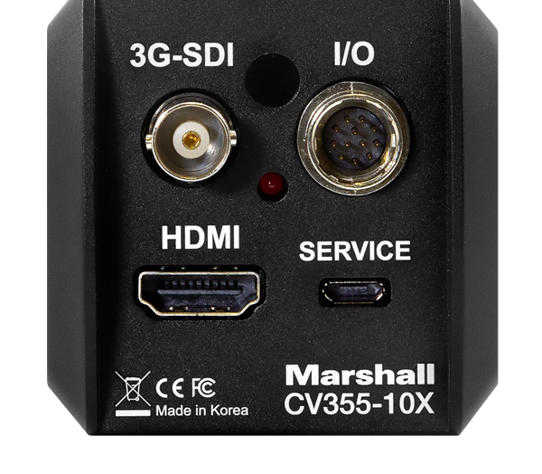
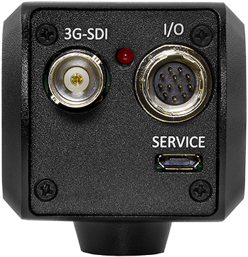
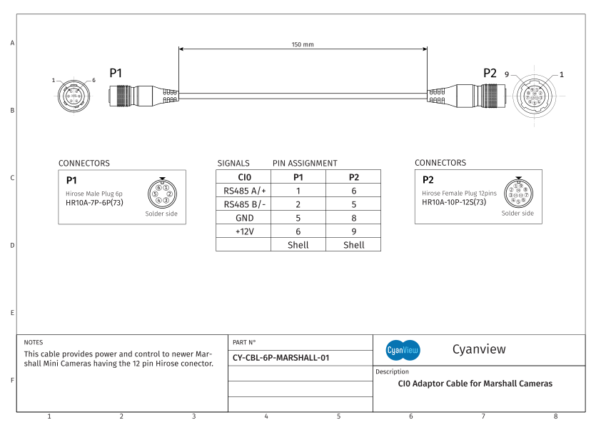
If your camera has a 12-pin Hirose connector on the back, use CY-CBL-6P-MARS-02:
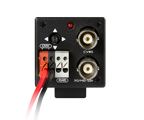
If your camera uses the Marshall Breakout Cable (DC 5.5×2.1 power jack + Phoenix block RS-485), use CY-CBL-6P-PFAN:
Cable wiring diagrams
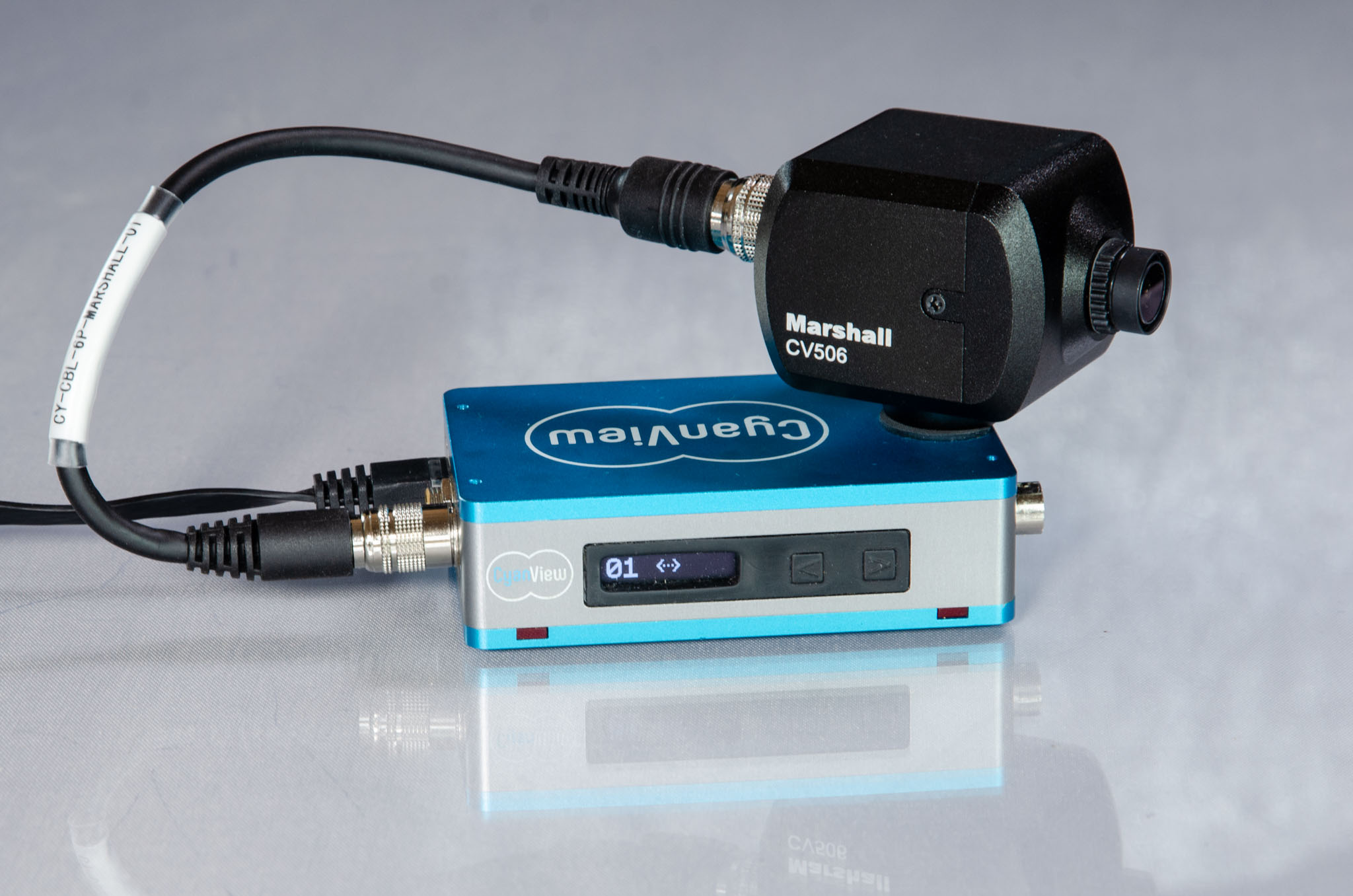
CY-CBL-6P-MARS-02 (12-pin Hirose):

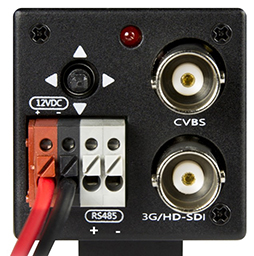
CY-CBL-6P-PFAN (Marshall Breakout Cable — CV225/CV226 and bullet cameras):
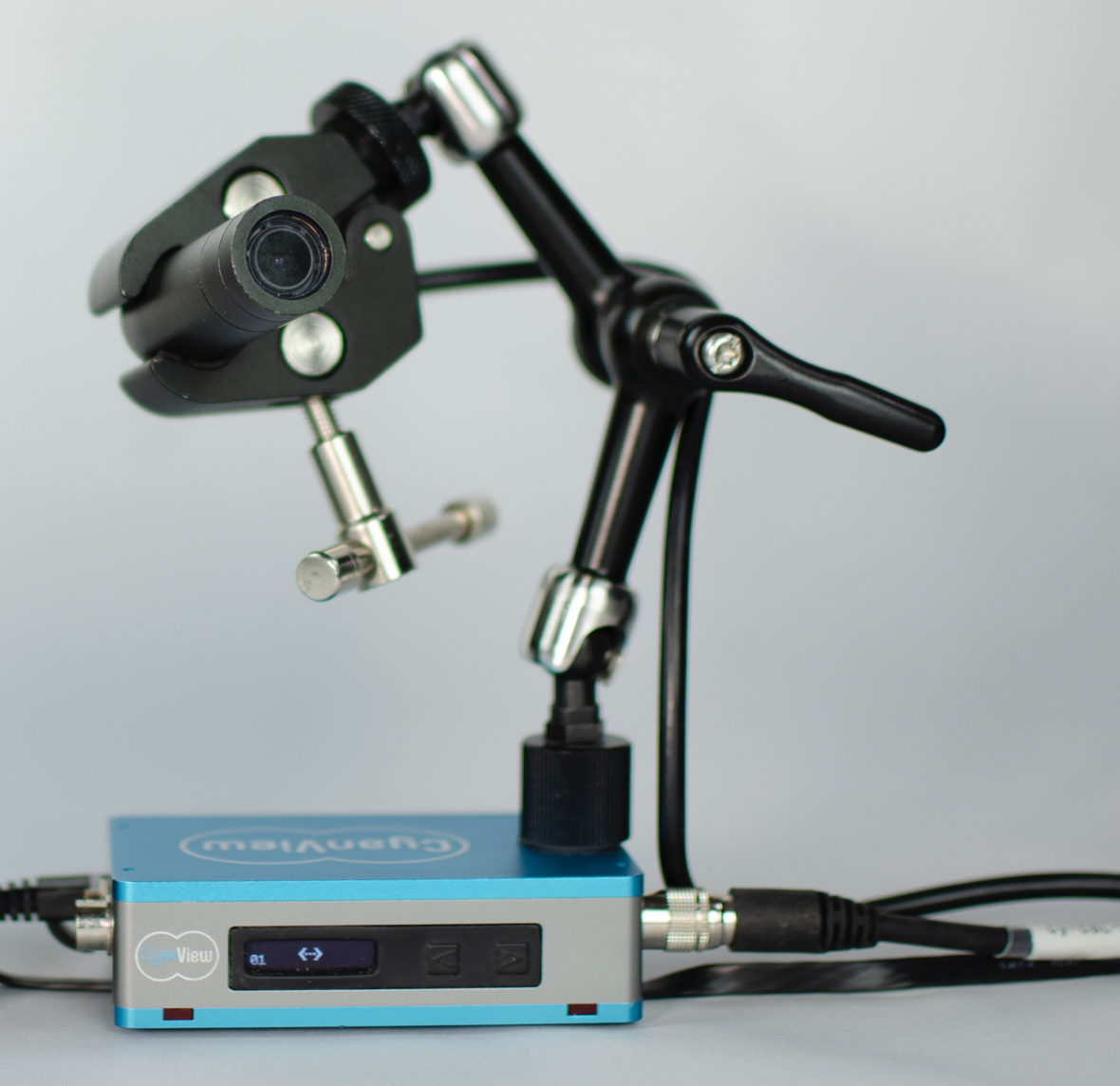
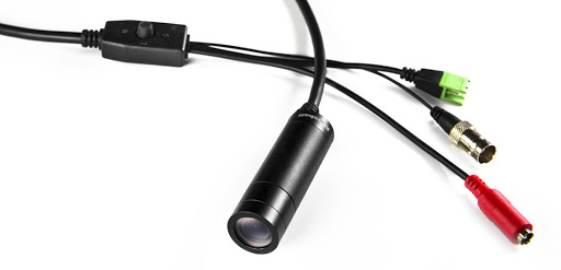

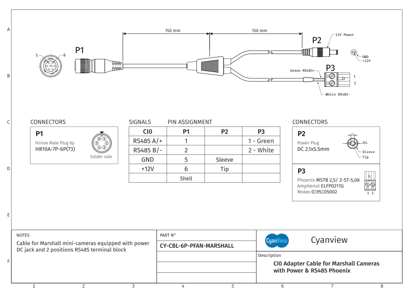
CY-CBL-6P-PFAN is a generic fanout cable with a separate DC jack for power. The cable does not come with the Phoenix block connector — Marshall provides it with the cameras. Follow the diagram to connect it.
CY-CBL-6P-FAN (push-lock connectors — CV502/CV530 and similar):
CY-CBL-6P-FAN is a generic fanout cable. Cut the yellow and blue wires not needed for this Marshall camera.
Configuration
Camera Configuration
Configure the following settings directly on the camera via the OSD menus:
Communication Settings
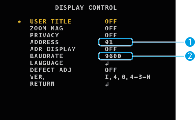
- [1] Camera address: Set to
01. This is the address used by the system in all modes except in a VISCA bus configuration with multiple cameras. - [2] Baud rate: Set to
9600bauds (default).
RS-485 communication runs at 9600 baud. One camera can be connected per CI0 serial port, and the camera address must match on each port.
RCP Configuration
Add serial models as a serial camera, or IP-enabled models as an IP camera.
Selecting the camera model
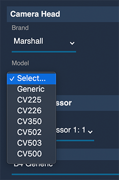
- Marshall Generic — Default choice for any Marshall camera. The model is auto-detected and available features are adjusted automatically. Requires a bidirectional connection (CI0 or RIO directly connected to the camera).
- Marshall CVxxx models — Use when the camera model cannot be auto-detected (e.g. unidirectional wireless or RS-485 over fiber systems).
Interface port
- Both ports of the CI0 or RIO support RS-485 and can be used.
- A USB RS-485 dongle plugged directly into the RCP is also supported.
Unidirectional mode
When the link between the RCP and camera is unidirectional (no data returns from the camera), the camera cannot be auto-detected and will stay RED. To allow sending commands without receiving responses:
- Click the 3-dot menu at the top right of the camera properties panel.
- Untick the Bidirectional option.
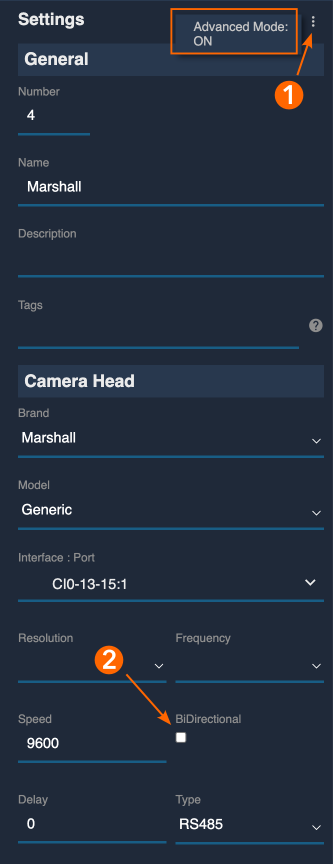
In this mode, select the explicit camera model (e.g. Marshall CV503) rather than Marshall Generic.
Multi-Camera / Bus Setup
VISCA allows up to 8 cameras to be connected on an RS-485 bus. When a VISCA bus is added and assigned to a CI0 serial port in the RCP configuration, up to 8 camera interfaces become available. Set each camera with a different address (see Camera Configuration) and select in the configuration GUI the corresponding port that matches the address.
Troubleshooting
Camera icon stays RED / camera not detected
Check in this order:
- Verify camera communication settings — confirm the baud rate is set to
9600and the camera address is1, unless you are using a VISCA bus with multiple cameras (see Camera Configuration). - Check the cable and pinout — if you made your own cable, refer to the cable diagrams to confirm the wiring is correct.
- Test for hardware issues — it is not uncommon for some cameras to have a defective RS-485 interface. Compare behavior with another unit of the same model, or test the camera using Marshall's control software with a USB-to-RS-485 adapter.
- Old firmware limitations — some older camera models or firmware versions do not acknowledge commands or send return data. The camera may not be "detected" but can still respond to control commands.
To test command reception without relying on feedback:
- Select the Marshall Generic model from the dropdown.
- Disable bidirectional communication.
- Use the
Camera > Menubutton on the RCP — all Marshall cameras share the same OSD open command, which confirms control is working.
The camera is in black and white
The camera is likely in auto DAY/NIGHT mode and has switched to black and white due to low light. Set it to DAY mode and save as user defaults to prevent recurrence:
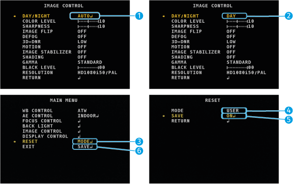
- In the
IMAGE CONTROLmenu, selectDAY/NIGHTmode. - Change value from
AUTOtoDAY. - From the
MAIN MENU, changeRESETfromONtoMODE, then press select. - Change
MODEfromFACTORYtoUSER— this changes startup settings from factory to user settings. - In
SAVE, selectONand press select — this saves current settings as user startup settings. - Exit the menus and save.
A specific parameter is not controllable
- Confirm the correct camera model is selected in the RCP — some controls are only available on specific models (see Supported Models).
- For models without a direct protocol control (e.g. Master Black on CV225), use the OSD menu via the RCP
Camera > Menubutton. - If the camera uses an old firmware version, it may not support all VISCA commands. Check Marshall's firmware release notes for the specific model.