CI0
The CI0 is an IP-to-serial camera interface. It connects serial cameras, lenses, and compatible accessories to an RCP, GWY, or RIO over the local network.
The CI0 does not run camera control software by itself. It receives commands from the RCP, GWY, or RIO and converts them to the serial protocol required by the connected camera or device.
For camera-specific cables, serial settings, and camera-side configuration, use the relevant camera integration guide and the Cables page.
To add a CI0-connected camera to an RCP configuration, follow Add a serial camera.
When To Use A CI0
Use a CI0 when the camera interface can stay on the same local network as the RCP, GWY, or RIO.
Typical uses:
- Control one serial camera from an RCP.
- Provide power and control to mini-cameras through the CI0 serial connector.
- Add Blackmagic SDI camera control when using a CY-CI0BM or an RSBM interface.
Use a RIO instead of a CI0 when the camera or lens needs a constant local control connection:
- Some Sony camcorders using the legacy 8-pin connector: some models have separate paint settings for standalone and remote operation. If the RCP connection is not stable, the camera may lose remote control or switch paint settings unexpectedly.
- B4 ENG lenses and Canon CineServo/Duvo lenses: the lens must stay in digital control mode. If communication is interrupted, the lens can fall back to analog control and close the iris. This can happen if the RCP is power-cycled or the Ethernet connection to the CI0 is disconnected.
CI0 Or RIO
The CI0 and RIO both provide serial camera ports, but they are designed for different workflows. The CI0 is a microcontroller-based IP-to-serial interface controlled by an RCP, GWY, or RIO. This gives it limited network capabilities. The RIO runs a full Linux operating system, includes the camera protocol software from the RCP, and can control cameras by itself, with the same two standard serial ports as the CI0. It is similar to an RCP and CI0 combined, without the user panel.
Because the RIO runs the camera protocol locally, it does not need constant communication with the RCP to keep a camera or lens connection alive. This is especially useful when the network adds latency, routing, wireless links, or remote transport.
| Use case | CI0 | RIO |
|---|---|---|
| Local IP-to-serial camera interface | Yes | Yes |
| Runs camera protocols and configuration locally | No | Yes |
| Has its own web configuration interface | No | Yes |
| Can control cameras over USB | No | Yes |
| Control of B4 or Cine Servo lenses | Not recommended | Yes |
| Control of Sony camcorders through 8-pin legacy connector | Not recommended | Yes |
| Can keep controlling the camera if the RCP link drops | No | Yes |
| Built-in Wi-Fi or USB modem workflow | No | Yes |
| Routed network or control through a gateway | No, requires local broadcast discovery | Yes |
| VPN or LAN tunnel with latency | Not recommended | Yes |
| REMI, cellular, or control over the internet | No | Yes |
| PoE power input | Yes | No |
| 12 V DC power input | Yes | Yes |
Choose a CI0 for simple serial control on the same local network as the RCP, GWY, or RIO. Choose a RIO when the camera position needs local intelligence, USB camera support, Wi-Fi or cellular connectivity, REMI pairing, or operation across a gateway, VPN, or internet link.
Do not use a CI0 with a layer-2 VPN or LAN tunnel. A CI0 may be discovered if the tunnel carries the required broadcast messages, but that does not make it a good remote-control interface. Some serial camera protocols require acknowledgements with short timeouts. With a CI0, those low-level protocol exchanges cross the tunnel. With a RIO, the camera protocol runs locally between the RIO and the camera; the RCP sends higher-level control commands to the RIO.
Models
| Model | Notes |
|---|---|
| CY-CI0 | Standard CI0 with two serial ports. |
| CY-CI0BM | CI0 with integrated Blackmagic SDI control. See the Blackmagic camera control guide. |
| CY-CI03P | Legacy variant kept for special development needs. The third port is not equivalent to the two standard CI0 serial ports. |
Using A CI0 On The Network
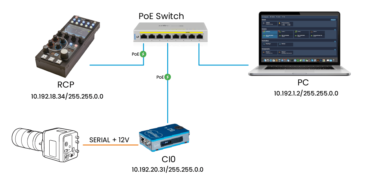
The CI0 is designed to be plug and play on a local Cyanview control network.
- Connect the CI0 to the same PoE switch or local network as the RCP, GWY, or RIO. When connected to a PoE switch, the CI0 is powered through Ethernet. Once it has network link but has not found the RCP yet, the screen shows
X. - The RCP automatically discovers the CI0 without manual IP configuration. Once the CI0 discovers the RCP, the screen shows
>-<. - When adding a serial camera, select the discovered CI0 and the port the camera is connected to. See Add a serial camera.
Once a CI0 is used in the configuration of one RCP, GWY, or RIO, it cannot be used by another controller until it is removed from the first configuration. If the CI0 is already taken by another controller, the screen shows <->. To share camera control between multiple RCPs, use the RCP REMI functionality instead of connecting several RCPs directly to the same CI0.
Network Behavior
The RCP and CI0 communicate using their factory IP addresses, so no IP configuration is needed for a normal local setup.
- The CI0 IP address is fixed from its serial number and is not meant to be changed.
- The CI0 announces itself on the network using a broadcast discovery message.
- An RCP, GWY, or RIO that has a camera configured on that CI0 can automatically use it.
- The CI0 does not have a manual REMI import workflow.
- Unlike a RIO, a CI0 cannot be controlled directly by multiple RCPs.
Required network access:
| Port | Protocol | Purpose |
|---|---|---|
| 3838 | UDP | Discovery |
| 1883 | TCP | Messaging |
| Dynamic | TCP | Serial communication |
The CI0 is not the right device for routed, VPN, cellular, Wi-Fi, or other high-latency links. Use a RIO for those workflows.
Power
The CI0 can be powered by PoE/PoE+ or by an external DC supply.
| Power source | CI0 input | Power available on serial ports |
|---|---|---|
| PoE or PoE+ | Ethernet port | Regulated 12 V DC, up to about 1 A total depending on the switch |
| External DC supply | 10-24 V DC input | The input voltage is passed through to the camera ports, it is not regulated |
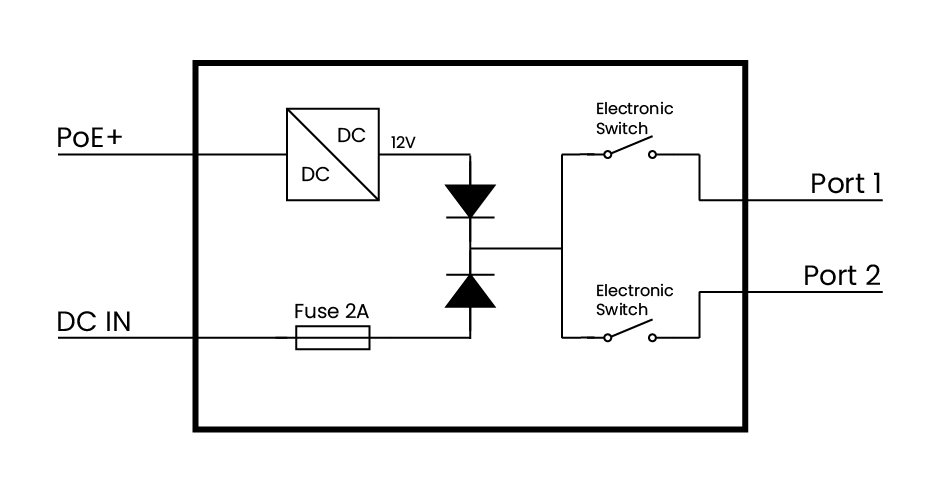
Important power limits:
- Camera consumption should not exceed 12 W per port for thermal reasons.
- When using the DC input, the supplied voltage is also present on the camera ports. Confirm that every connected camera or accessory supports that voltage.
- For power-hungry cameras or motorized lenses, PoE may not provide enough current. Use a dedicated DC supply when control drops, the camera reboots, or the lens initialization causes power spikes.
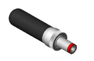
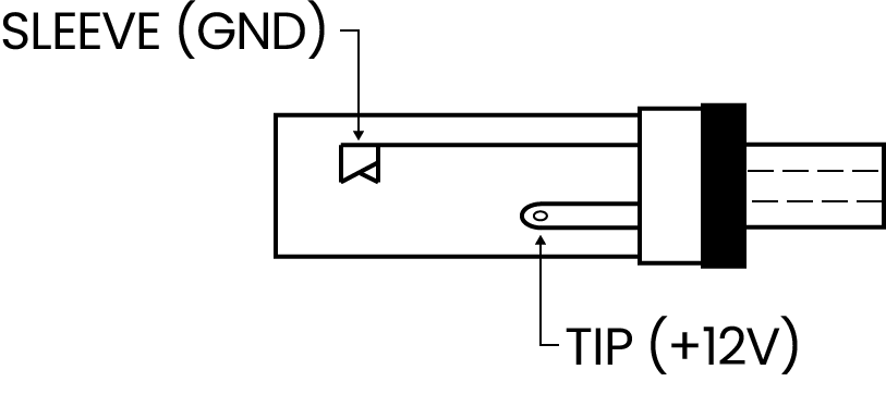
The DC input connector is a Switchcraft 762K or compatible 5.5 x 2.1 mm plug with locking screw. D-Tap to DC locking screw cables are commonly available. For custom cables, a Digikey 10-00110 cable can also be cut in half.
Serial Ports
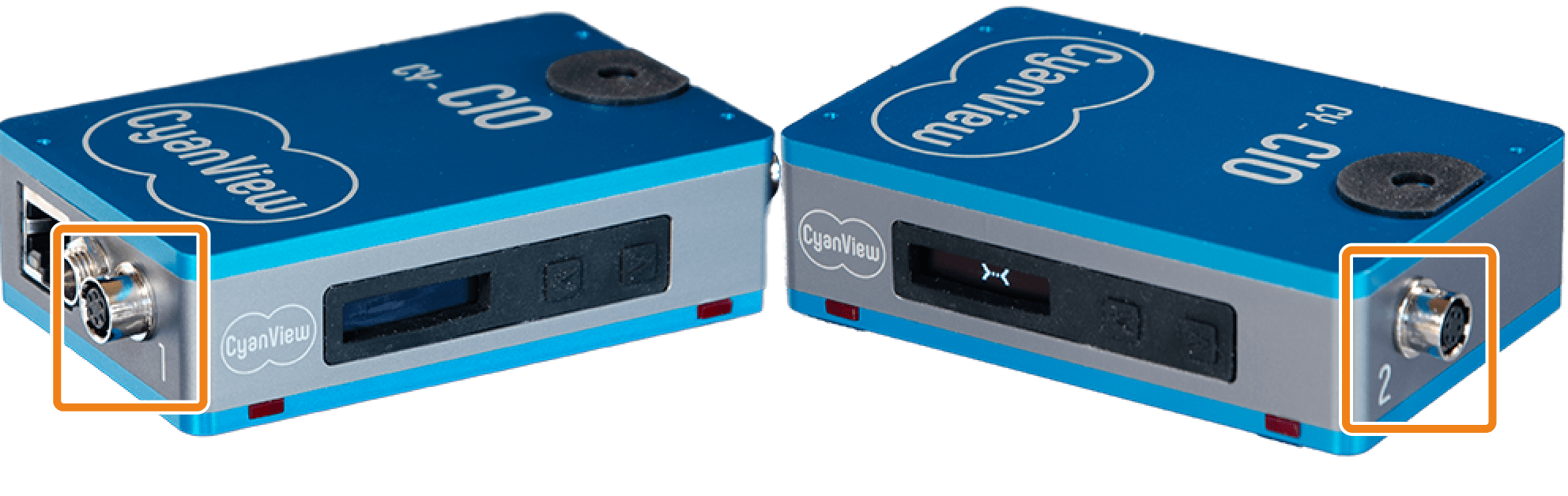
Connectors
| Item | Reference |
|---|---|
| CI0 serial connector | Hirose HR10A-7R-6S(73) |
| Mating cable plug | Hirose HR10A-7P-6P(73) |
Cyanview provides cables for supported cameras and accessories. See Cables and the relevant camera integration guide before building or ordering a cable.
If a serial connector is damaged, replacement connector assemblies are available from Cyanview. Contact sales@cyanview.com to order a spare part.
Pinout
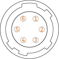 Female receptacle. | Pin | Protocol pinout | ||
|---|---|---|---|---|
| RS-232 | RS-422 | RS-485 | ||
| 1 | Y / TX+ | A / + | ||
| 2 | TX | Z / TX- | B / - | |
| 3 | RX | A / RX+ | ||
| 4 | B / RX- | |||
| 5 | GND | GND | GND | |
| 6 | 10-24 V DC out +12 V on PoE | 10-24 V DC out +12 V on PoE | 10-24 V DC out +12 V on PoE | |
| Shell | ||||
Supported Protocols By Port
| Port | RS-485 | RS-232 | RS-422 | LANC | SBUS | B4 lens |
|---|---|---|---|---|---|---|
| P1 | Yes | Yes | Yes | No | No | Yes |
| P2 | Yes | Yes | Yes | Yes | Yes | Yes |
Some camera protocols are only available on a specific CI0 port. Check the camera integration page before wiring the camera.
Pin 6 Power and Tally Output
Pin 6 on each serial port carries the supply voltage used to power cameras and accessories. See Power for voltage levels and limits depending on the CI0 power source.
When the CI0 is powered from a DC supply, the input voltage is present on pin 6 of every connected port. Confirm that every connected camera or accessory supports the supplied voltage before connecting.
By default the output on each port is always active. It can also be switched independently using an internal transistor. Using the GPIO page in the RCP or RIO web interface, the output can be configured as a GPO driven by tally state. This allows a tally light connected to pin 6 to turn on and off when the camera is on-air.
Supported Serial Topologies
One Camera
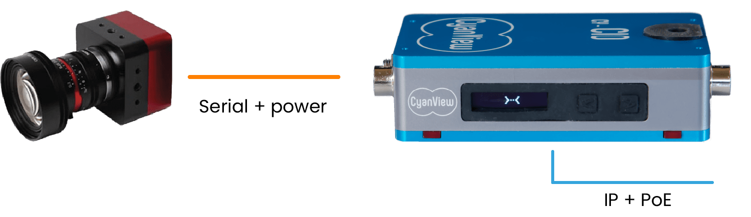
This is the standard setup: one camera connected to one CI0 port.
A Camera On Each Port

A standard CY-CI0 can control one serial camera on each of its two ports. A CY-CI03P can expose a third port for supported workflows.
Serial Bus
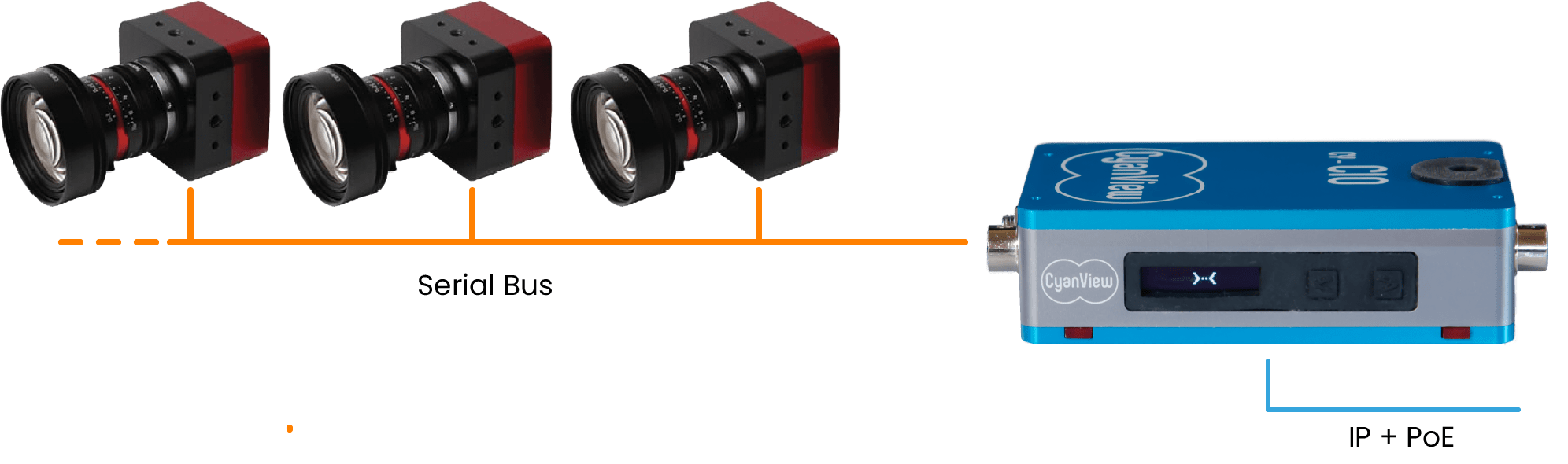
Some protocols support several cameras on one serial bus. Each camera must have a unique address, and the bus must be wired and terminated according to the camera manufacturer's requirements.
Status Screen
The side LCD shows CI0 network and camera-port status.
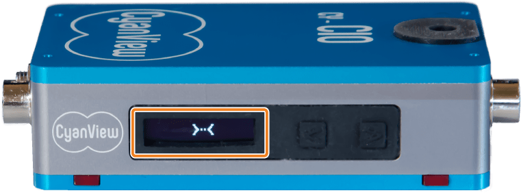
| Screen | Meaning |
|---|---|
 | CI0 is waiting for a network connection. |
 | CI0 is connected to the network but cannot communicate with the RCP, GWY, or RIO. |
 | CI0 has discovered an RCP, GWY, or RIO but is not yet assigned to a configured camera. |
<-> | CI0 is already used by another controller and is not available to this RCP, GWY, or RIO. |
 | Camera 01 is configured on port 1 but is not connected. |
 | Camera 01 is connected on port 1. |
 | Camera status shown on the right side corresponds to port 2. |
 | On a CY-CI03P, the middle position corresponds to port 3. |
Press either button beside the screen to cycle through the camera name on port 1, the camera name on port 2, the CI0 IP address, and the CI0 MAC address. The screen returns to the default status after a few seconds.
Firmware Updates
CI0 firmware is updated automatically by the RCP or GWY when the CI0 is added to a configuration and the required firmware version does not match the installed version.
You normally do not need to manage the CI0 firmware version manually.
Force A Firmware Update
Use this procedure only when the CI0 firmware needs to be recovered or refreshed.
Make sure an RCP, GWY, or RIO is on the same network as the firmware update will be sent by this device to the CI0.
- Hold both CI0 buttons while powering the CI0.
- Keep the buttons pressed for 5 seconds.
- Release the buttons.
- If the LEDs blink, the CI0 is in bootloader mode.
- Wait up to 1 minute for the CI0 to restart and display
>-<.
Troubleshooting
For general diagnostic steps, see Troubleshooting.
CI0 Does Not Start
A working CI0 should show:
- RJ45 steady green LED for a 100 Mbps link.
- RJ45 blinking orange LED for network activity.
- LCD status such as
>-<,<->, or camera numbers.
Checks:
- Check the Ethernet and power wiring.
- Put the CI0 and RCP, GWY, or RIO on the same switch for a local test.
- If using PoE, try an external 12V DC power supply.
- If using a 12 V DC power supply, try another supply.
- If the CI0 is visible on the network but behaves incorrectly after an update, force a firmware update.
Screen Shows X
X means the CI0 has a network link but cannot communicate with the RCP, GWY, or RIO.
Checks:
- Confirm the RCP, GWY, or RIO is on the same reachable network as the CI0.
- Check Ethernet link and activity LEDs.
- Make sure UDP port 3838 is not blocked.
- Check whether the CI0 appears on the RCP discovery page. See What is discovery?.
- If the issue started after an update, force a firmware update.
- On managed or routed networks, check for ARP, VLAN, firewall, or Proxy ARP behavior that may block local discovery or redirect traffic.
CI0 Is Not Listed In The Camera Interface List
If the CI0 does not appear when adding a camera, it has not been discovered yet or is not reachable on the local network.
Checks:
- Make sure the CI0 and RCP, GWY, or RIO are on the same local network.
- Check the CI0 screen: it should show
>-<when it has found the RCP. - If the screen shows
<->, the CI0 is already used by another controller.- Remove the CI0 from the camera configuration on the RCP, GWY, or RIO that currently uses it.
- If you do not know which controller is using the CI0, check the diagnostics page of the RCP web interface — it should be listed there.
- Reboot the CI0.
Camera Control Drops Or Camera Reboots
This is often a power issue. See Power for supply limits and connector details.
Checks:
- Switch from PoE to a dedicated DC power supply.
- If several cameras are connected to the same CI0, disconnect them and reconnect them one by one.
- Check whether the camera or motorized lens has a startup current spike.
- Confirm that the camera supports the voltage supplied through the CI0 port.
Screen Is Permanently Dark
On some units a display PCB defect causes the LCD to remain dark even when the CI0 is powered and operating normally. A dark screen does not affect camera control.
To verify the CI0 is functional:
- Check whether the CI0 appears on the RCP discovery page. See What is discovery?.
- Ping the CI0 IP address from a device on the same network.
- If the CI0 responds on the network and cameras can be configured and controlled normally, the unit is working.
If the screen is permanently dark and the CI0 is otherwise functional, return the unit for screen repair. See the RMA procedure.
Serial Port Connector Is Damaged
If a CI0 serial port connector is damaged, replacement connector assemblies are available from Cyanview. See Serial port connectors for the connector reference. Contact sales@cyanview.com to order a replacement.
Unsupported Custom IP Configuration
Changing the CI0 IP address is not a supported solution and should not be used to make a CI0 fit a routed, VLAN, VPN, or complex network design.
The CI0 is designed to use its factory IP address and local broadcast discovery. If you need more network control, routing, VLAN handling, REMI operation, or remote connectivity, use a RIO instead. See Configure IP addresses for RCP and RIO network configuration.
This advanced procedure has helped a few installations with exceptional constraints, such as an IP conflict or a site security requirement. Use it only if you understand the risk and can recover the CI0 locally.
Set A Custom CI0 IP
- Connect the RCP and CI0 to the same local network or switch.
- Add a camera on the CI0 by following Add a serial camera.
- Add the target network range to the RCP by following Configure IP addresses. The RCP can have multiple IP addresses on the same LAN interface.
- Open the RCP advanced firmware page:
http://10.192.xx.xx:5000/firmware/index.html, replacing10.192.xx.xxwith the RCP IP address.
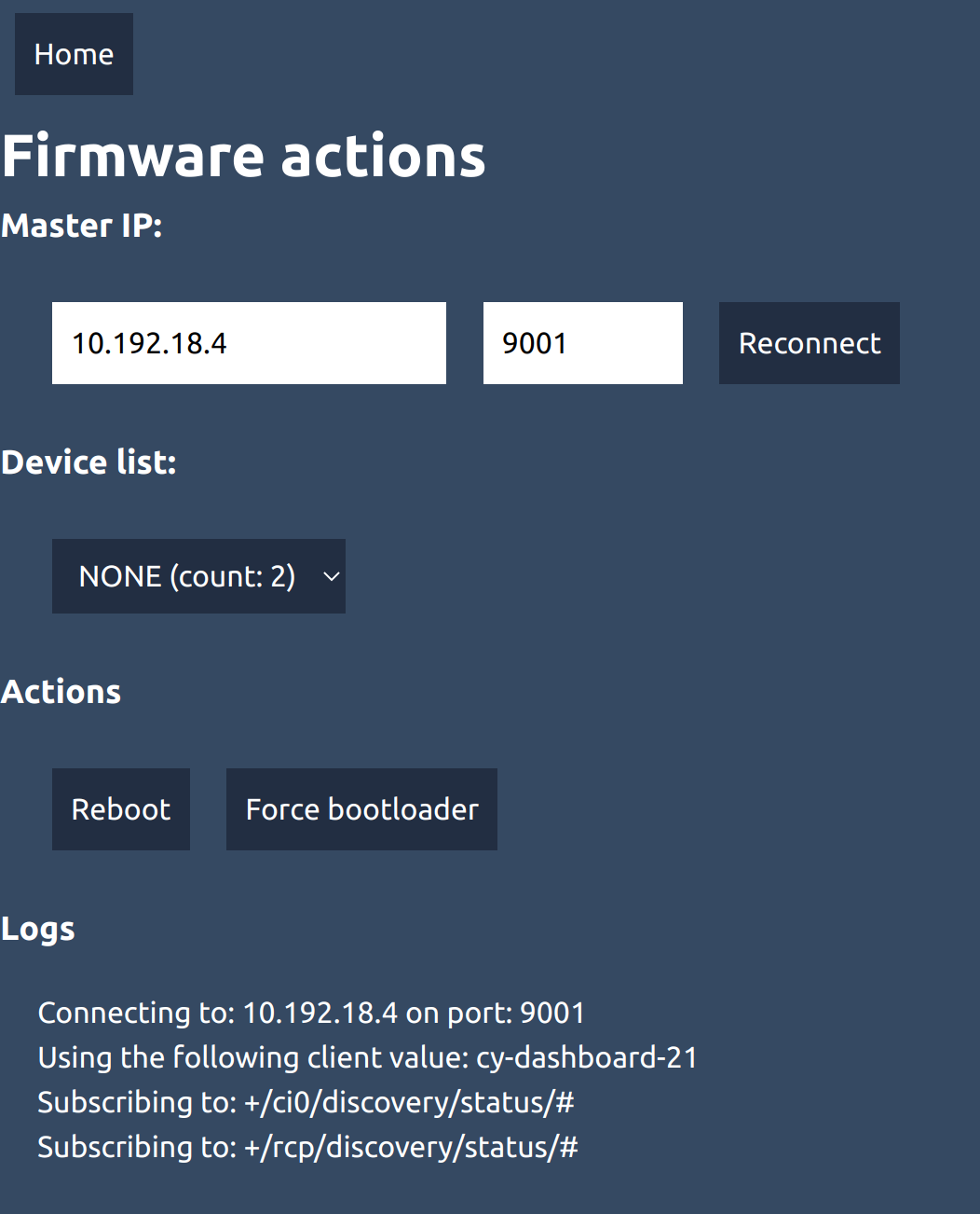
- In Device list, select the CI0 serial number.
- If the CI0 is not listed, wait a few seconds and try again. Discovery can take up to 30 seconds.
- In the Change default IP section, enter the new CI0 IP address and mask.
- If needed, enable the gateway field and enter a gateway. The default gateway value is
0.0.0.0. - Click Set IP.
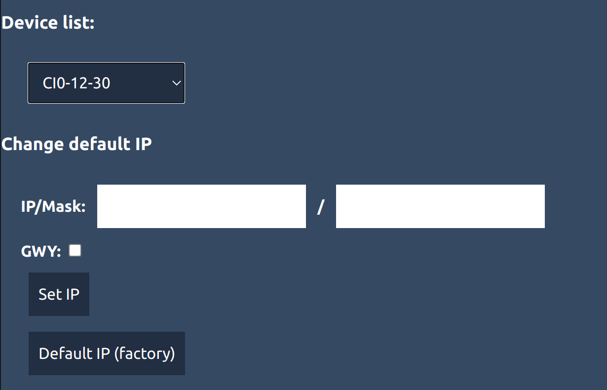
- Review the confirmation window carefully. Click OK to apply the change, or Cancel to modify the values.
- Confirm that the camera connected to the CI0 is still controlled correctly.
- Move the CI0 to its final location only after confirming control.
You can repeat this procedure to change the custom IP, mask, or gateway again.
Reset The CI0 IP To Factory Default
To reset from the RCP advanced firmware page:
- Open
http://10.192.xx.xx:5000/firmware/index.html, replacing10.192.xx.xxwith the RCP IP address. - Select the CI0 in Device list.
- Click Default IP.
To reset with the physical buttons:
- Hold both CI0 buttons while powering the CI0.
- The CI0 enters bootloader mode using the default IP.
- The IP address is restored to the factory value after the bootloader starts.